120v Switch Wiring Diagram For Coffee Maker Led Resistor
I'd like to show the following diagram. There is no concern about which end of the resistor is connected to power, and which to ground.
Weldon Technologies 6201003000 VMUX Multiplex Controller Screen Display

A resistor in series with the cap would keep any initial charging current to a safe level to avoid killing the diodes.
120v switch wiring diagram for coffee maker led resistor. Each part ought to be placed and connected with other parts in specific way. Such a resistor is often called a ballast resistor. Its very simple to use.
And here's what the switch looks like ideally when operated. Each part should be placed and linked to different parts in particular manner. I'm also thinking of adding a 12v switch with an led.
This is only an example. If the voltage source is equal to the voltage drop of the led, no resistor is required. Leds are also available in an integrated package with the correct resistor for led.
Otherwise, the structure will not work as it. A coffee maker is a appliance that brews coffee from cold water and ground coffee beans. For example, a switch would have been a burglary the road having a line in an angle for the wire, much like a light switch you’ll be able to flip on / off.
This is the diagram i drew of it. The diagram above shows a two conductor cable from the circuit breaker panel going to a wall switch. Heat up the cold water used to make that coffee.
Connect transformer to low voltage led wiring : No problem with that, but as i am going to put apart and rewire a coffee machine, pretty dangerous heating device after all, i wanted to fully understand its wiring diagram beforehand. Seamless circuit design for your project.
Wiring diagram book a1 15 b1 b2 16 18 b3 a2 b1 b3 15 supply voltage 16 18 l m h 2 levels b2 l1 f u 1 460 v f u 2 l2 l3 gnd h1 h3 h2 h4 f u 3 x1a f u 4 f u 5 x2a r power on optional x1 x2115 v 230 v h1 h3 h2 h4 optional connection electrostatically shielded transformer f u 6 off on m l1 l2 1 2 stop ol m start 3 start start fiber optic. Scottyuk (electrical) 21 mar 07 12:27. Led turn signal load resistor wiring diagram (turn signal only) led turn signal load resistor wiring diagram (stop/turn signal) a typical load resistor for a 21 watt turn signal light bulb would have a rating of 50 watts, 6 ohms.
So, please check with your supplier, to ensure the correct size is obtained. The 1 kilohm resistor is used to avoid possible current peaks and its effect is negligible as most of the voltage drop is in the capacitor. The wiring diagram for the switch is as follows:
This is the safer better way to wire leds in parallel with resistors and also ensures that you dont make the mistake that i did accidentally. In order to understand how the circuit works, we will start drawing the circuit diagram or. An antiparallel diode across the led and a series capacitor is probably the lowest loss way of doing this.
Lower wattage of resistor like 1/2 watt or lower will not do and may burn since they are meant for 6v dc circuits, not for 220v ac mains. And today this can be the primary image. Connect black anode of diode to negative of the led.
11 arduino circuit diagram maker online. Draw circuit diagram online arduino. I had the resistor sized in my diagram to remove 60 ma of current (i think).
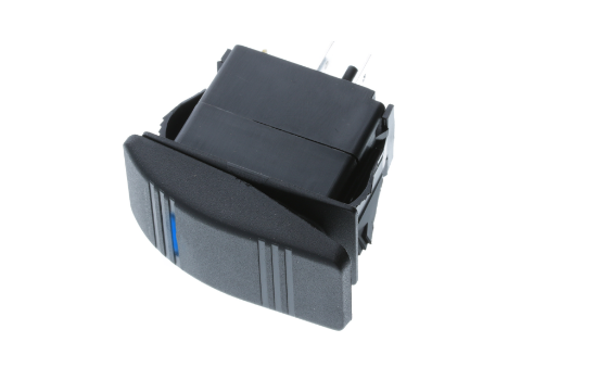
Current is measured in amps and the leds contained in the kit can handle a maximum current of 20ma. We will be using a 330 ohm resistor for now. I could understand that the three pin device in the middle is a rocker switch.
Otherwise, the arrangement won’t function as it ought to be. 120 and 240vac led voltage indicator circuit diagram circuit and wiring diagram download for automotive car motorcycle truck audio radio electronic devices home and house appliances published on 13 jul 2014. From the ceiling box an electrical receptacle outlet is fed power.
Open transformer and remove knockout holes to gain access to internal wiring to install: The ballast resistor is used to limit the current through the led and to prevent excess current that can burn out the led. Connect the resistor to the positive of the led.
Connect the free ends of the diode and resistor to the male pins. Using the enclosed quick connects, connect one end of the resistor to the power wire, and the other end of the resistor to the ground wire. That will drop voltage and reduce current further, so i'll need to recalculate for the resistor.
Power the thermostat that measures the temperature of the water and disconnects the circuit to keep it from over heating. Slip the quick connect onto the vehicle. See diagram the resistor can be installed in either direction.
Light switch wiring diagram depicted here shows the power from the circuit breaker panel going to a wall switch and then continues to a ceiling light with a three conductor cable. Mark the extension wires with colored tape to identify switch wires (both ends). Send the boiling water to the filter.
A resistor is going to be represented using a compilation of squiggles symbolizing the restriction of current flow. How to power led with 120 volt a/c supply. Keep the heating pad ,located under the pot, heated.
We have collected numerous images, ideally this photo serves for you, and help you in locating the solution you are seeking. Diagram of the connected holes of a breadboard wire led resistor led circuit. This means that we need a way to limit the current in the circuit and this can be done using a resistor.
Switch Components Inc Electromechanical Switches Global Supplier

Part of the 8008's instruction decode PLA. The three indicated transistors match opcode pattern

17 Best images about 12V on Pinterest 12 volt solar panels, Ice makers and Led light fixtures

Switch Components Inc Electromechanical Switches Global Supplier

EMI 12BPT1066 48

Pinned onto

27 Lutron Single Pole Dimmer Switch Wiring Diagram Wire Diagram Source Information

Piping Technology PTP290B Standard Variable Spring Hanger 200LBS/in size 90

Die photo of the 8008 microprocessor, showing important functional blocks.

Hunter DSP400 Wheel Alignment Clamp w/ Target Reflector 17

Switch Components Inc Electromechanical Switches Global Supplier

Eaton Vickers 300AA0085A 110VAC Electric Solenoid Switch Control

OEM Motorcraft BRRF115 Front Disc Brake Rotor & Hub For E350 Super Duty 0816

Whelen SA314 100W Siren PA Loud Speaker 01088351300 122DB

Baldor Reliance 1YAB30108A1 Duty Master Electric AC Motor 230/460V 3PH 7.5 HP

Switch Components Inc Electromechanical Switches Global Supplier
Heating element 12v 120c Sun Kist Enterprise

Hertner 3SE12775 24VDC Forklift Battery Charger 775AH 153A 1PH

Cat 0775482 LH Left Side Control Limit Switch SPDT w/ Wobble Coil Spring
