Duraspark Ignition Module Wiring Diagram
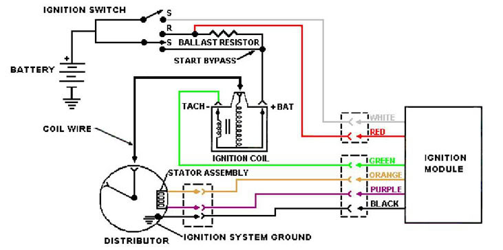
A factory fe distributor with a duraspark electronic conversion and a large cap. Power is supplied to the coil in the same fashion as the older breaker point ignition.
please help duraspark ignition no spark Ford Mustang Forum

It's a simple series circuit so it shouldn't make a difference, but i think i'd connect the orange to a and the purple to c.

Duraspark ignition module wiring diagram. #6 · sep 25, 2008. It contains instructions and diagrams for various types of wiring methods as well as other items like lights, home windows, and so on. Wiring diagrams wiring schematic for module to assortment of gm body control module wiring diagram.
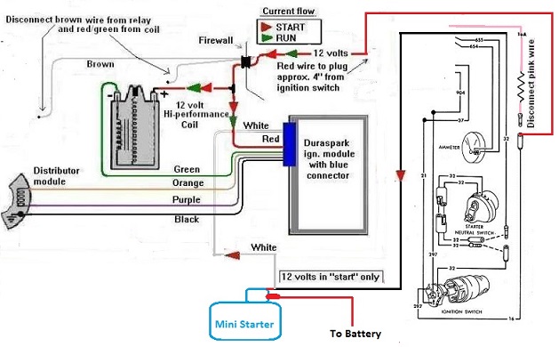
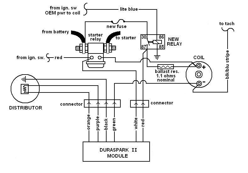
It can be used with both the large cap and small cap early electronic distributors. The red wire which is connected to a switched 12v source and the white wire which goes to the start terminal of the ignition switch. Shown here on the firewall of my '72 bronco.
Be sure to get the wiring harnesses connecting the module, distributor, and coil, as well as the male end. The system consists of the distributor coil external amplifier box wiring and connectors. Not sure of the right wires to tap into.
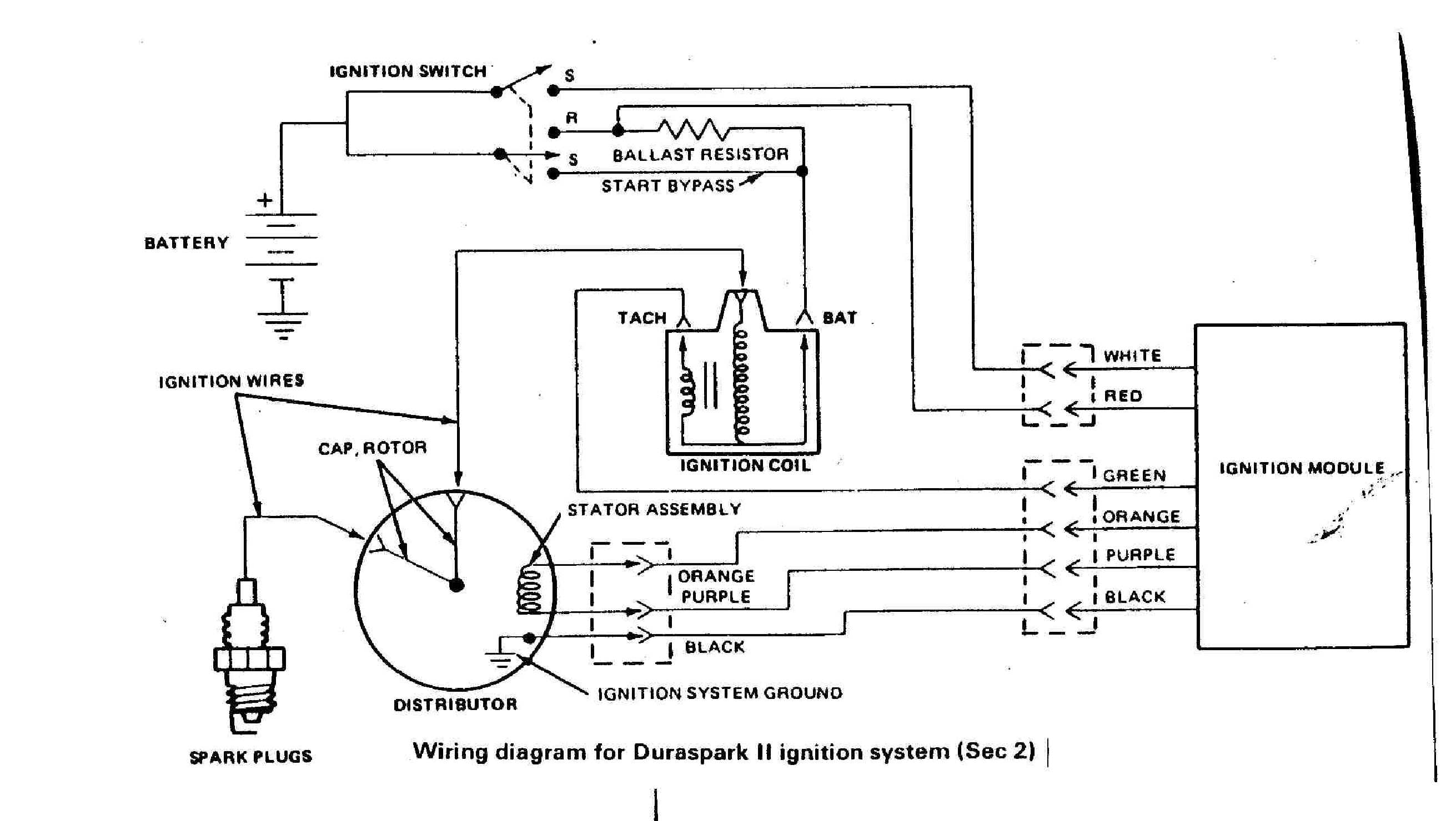
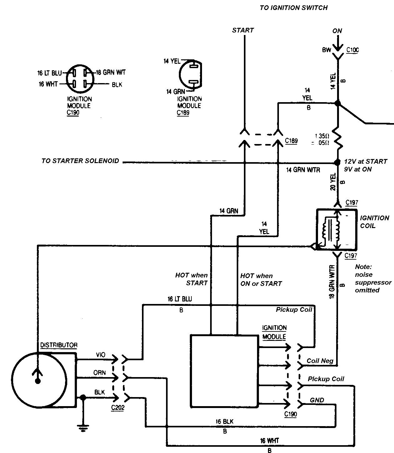
Some 1981 and later duraspark ii systems used with the 5 0l engine are quipped with a universal ignition module. It appears that the 1966 ford factory original pink resistor wire will not be used. Test the resistance of the ground circuit by probing the black wire at the module and distributor.
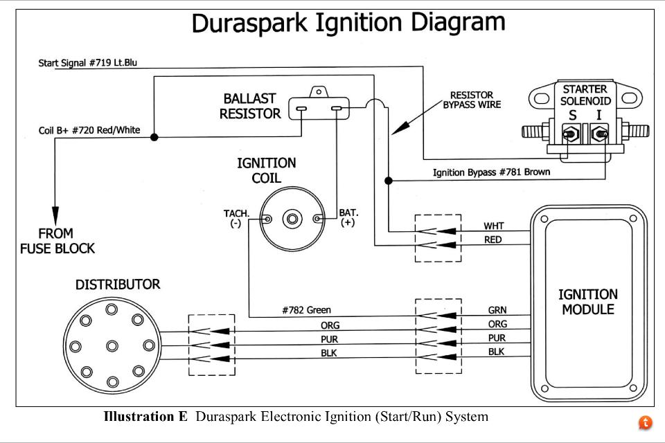
Here is the diagram provided by painless for the duraspark system now, here is one that is widely found on the internet the big difference in the diagrams is how the starter solenoid is wired to the ignition module. Duraspark ii ignition harness connect the components in ford electronic ignition systems using the in the diagram, a wire from the ignition switch.sep 25, · a duraspark ii setup requires full bat vlt to the module (keyed through ign sw) and if using a duraspark ii coil, it (coil) must be run through a resistor. Run a positive feed wire from ignition switch, for when key is in the on position, to the ignition module (red wire coming out of ignition module).
Ford 390 duraspark ignition wiring diagram. It is meant to work in place of the duraspark ignition module. I have it running and stuff but i cannot seem to make the tachometer work.
The culprit was our stock duraspark distributor which we then replaced with a custom calibrated unit from performance distributors. Its a ford engine with c4 tranny, with stock type electronic ignition from a. The duraspark ii distributor uses a magnetic pickup in place of traditional breaker points.
A wiring diagram is a simplified standard pictorial depiction of an electrical circuit. The white wire is optional. A duraspark ii setup requires full bat vlt to the module (keyed through ign sw) and if using a duraspark ii coil, it (coil) must be run through a resistor.
Repair this circuit if readings exceed 0.3 ohms. Would like to know if i can splice into a wire under the hood/and what one , or if i have to go all the way to ignition switch to splice in. Distributor s yfass coil puqp e system ground orange purple black ignition module
This duraspark ii ignition harness is designed to connect the components in ford electronic ignition systems using the “blue strain relief” ignition module.sep 25, · a duraspark ii setup requires full bat vlt to the module (keyed through ign sw) and if using a duraspark ii coil, it (coil) must be run through a resistor. Most installs only need two connections. Posted by patrickfa122 on dec 29, 2012.
This ignition system is a popular swap into earlier cars and trucks. It can be used with both the large cap and small cap early electronic distributors. Repair the circuit if readings are less than battery voltage.
The painless provided diagram shows the i terminal on the solenoid wired to the white wire coming out of the ignition module. Duraspark wiring diagram wiring diagram is a simplified good enough pictorial representation of an electrical circuit it shows the components of the circuit as simplified shapes and the power and signal connections amid the devices. Freightliner m2 bulkhead module diagram run a positive feed wire from ignition switch, for when key is in the on position, to the ignition module (red wire coming out of ignition module).
It shows the components of the circuit as simplified forms, and the power as well as signal links in between the devices. The duraspark ii ignition coil is capable of generating a higher voltage than the regular coil. Wiring it up is quite straightforward.
The ignition module performs the function of turning off current flow through the ignition coil in vacuum advance stator y. The duraspark ii ignition coil is capable of generating a higher voltage than the regular coil. This is most easily accomplished by making a trip to your favorite junkyard and rounding up all the parts.
Disconnect the negative battery cable. Here is the duraspark ii directions and it plainly states to use the ballast resistor ( pink wire) this duraspark ii ignition harness is designed to connect the components in ford electronic ignition systems using the “blue strain relief” ignition module. The black wire shown from the inductive proximity sensor is the ground and is the same as the black wire from the duraspark trigger.
The blue and brown correspond to the purple and orange wires. I am in the process of installing duraspark ii electronic ignition in my 1966 ford f100 and have a few questions. The painless wiring kit is supplied with a ballast resistor.
The ignition wiring diagram looks daunting but its not really that difficult. 1996 3.8 mustang , adding a 302 carb , need help on a basic wiring diagram to wire in a duraspark module. I am using painless wiring #30812 conversion kit.
The wh wire is an ignition timing retard to make staring the engine a little easier on the starter motor. Probe the red wire leading to the ignition module with the ignition switch in the run position to ensure a proper voltage signal. The standard base part number for this module is 12a199.
This duraspark ii ignition harness is designed to connect the components in ford electronic ignition systems using the “blue strain relief” ignition module.
Duraspark I ignition module Page 3 Ford Truck Enthusiasts Forums
Duraspark ignition and painless wiring harness HELP! CJ8

Duraspark 1 Wiring Diagram 38
Duraspark II The Ford V8 Engine
Ford Duraspark Ii Wiring Diagram
Painless harnes+duraspark Forums

33 Duraspark Wiring Diagram Wiring Diagram List
Ford Duraspark Ignition Wiring Diagram
[FC_3385] Duraspark Hot Wiring Free Diagram

Duraspark conversion questions Ford Truck Enthusiasts Forums
2.3 Ford Install
Ford Duraspark Ignition Wiring Diagram
Ford duraspark ii ignition system

Ford Duraspark Ignition Module Wiring
Dura Spark II
33 Duraspark Wiring Diagram Wiring Diagram List

Ford Duraspark Ignition Module Wiring

Duraspark ignition and painless wiring harness HELP!
29 Duraspark Wiring Diagram Worksheet Cloud