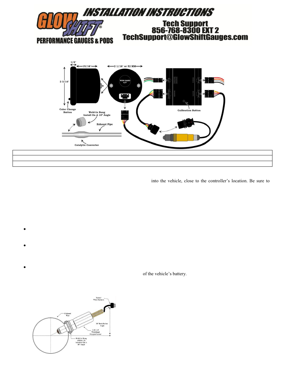
Air Fuel Ratio Sensor Wiring Diagram
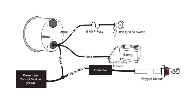
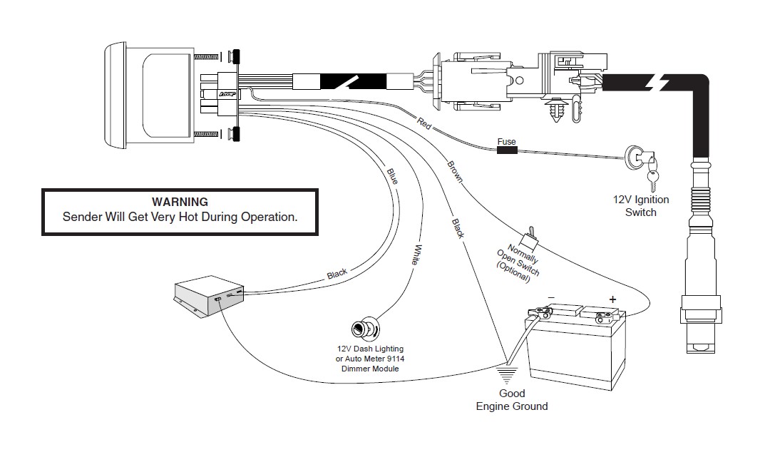
Connect to vehicle wiring harness, not oxygen sensor since some oxygen sensors use shielded wire. Connect to a fused and switched 12v positive source that is turned on and off with the ignition switch.
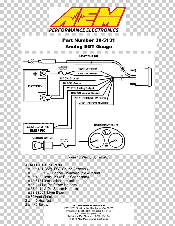
Aem Air Fuel Gauge Wiring Diagram
At this ratio, theoretically, all available oxygen in the air combines with all available fuel.

Air fuel ratio sensor wiring diagram. Neither will change significantly during mixture variations. Install the sensor in a location where the exhaust Disconnect vehicle battery before installation.
In nearly all oxygen sensors, a lean mixture (greater than 14.7:1) causes the oxygen sensor output voltage to drop, while a rich mixture (less than 14.7:1) causes the sensor output to go up. Autometer wideband wiring diagram 11 12 2018 11 12 2018 3 comments on autometer wideband wiring diagram auto meter cobalt wideband air fuel ratio gauge analog all i found that the factory oxygen sensor wiring was a secure location to. Inside the maf meter, there is a heated platinum wire which is exposed to the flow of intake air.
Strip 1/4 inch of the insulation off of the wire so that you can connect it. Air fuel ratio sensor problems 12v ignition switch good engine ground wide open throttle switch (for wot peak function) data logger output red.
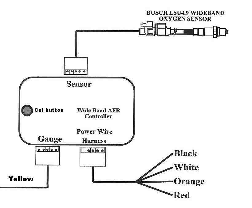
Connect to dash lighting dimmer control. Our specially designed o2 sensor and wiring harness are included for ease. In this diagnostic quick tip, national field trainer jason gabrenas shows you how to test.
Red to indicate a lean condition, green to Wire gauge as shown in diagram. The led colors represent the current air/fuel ratio condition;
So i tried tapping each wire on the o2 sensor and they all just get stuck on rich. Air/fuel ratio gauge connections the air/fuel ratio gauge face has two columns of 10 colored leds. 12v on one heater wire, and a computer controlled ground on the other, just like your typical heated o2’s.
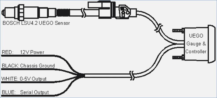
The black wire should be grounded to a solid ground source. Baud rate is 9600 bps, data bits is 8, no parity and stop bits is 1 (9600 8n1). By comparison, a wideband o2 sensor or a/f sensor provides a gradually changing current signal that corresponds to the exact air/fuel ratio.
Connect to good engine ground. Gasoline 14.7 lpg (propane) 15.5 methanol 6.4 ethanol 9.0 cng 17.2 diesel 14.6 the measurement lambda is the actual air fuel ratio over the stoichiometric. Pounds of air for every pound of fuel.
The goal of the oxygen sensor is to help the engine’s fuel management system approach or maintain the ideal 14.7:1 stoichiometric air to fuel ratio. 2004 civic air/fuel ratio problem. Voltage jumps up to 0.8 to 0.9 volts when the air/fuel mixture is rich, and drops to 0.3 volts or less when the air/fuel mixture is lean.
An air/fuel ratio sensor is much like an oxygen sensor, or o2 sensor, and is slowly replacing them on many vehicles. Modern air/fuel ratio sensors can be difficult to test and inspect. Brown wire (heater override for applications that provide less than 12.5 volts with engine running):
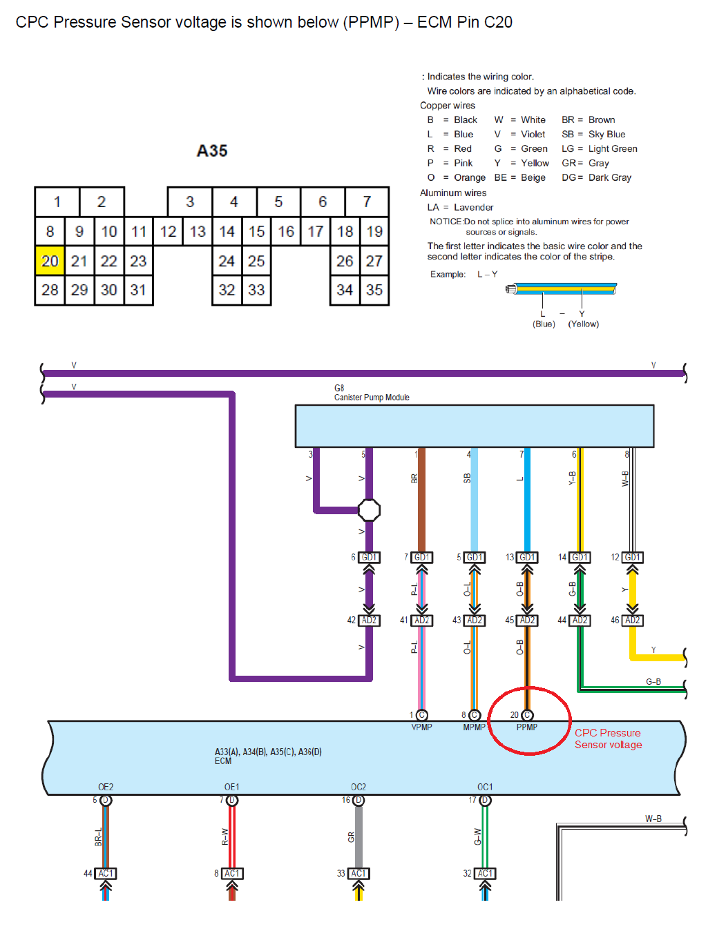
Is there a wiring diagram for that? Stoichiometric for different fuels are as follows: The terminals were listed as a/f sensor 1, a/f sensor 1, a/f sensor htr, and a/f sensor htr.
Connect to oxygen sensor signal wire. Based on air fuel ratio sensor signal, the computer adjusts the air to fuel ratio to keep it at the optimum level, which is about 14.7:1 or 14.7 parts of air to 1 part of fuel. Secure with supplied bracket and hardware.
In a naturally asperated engine, the finer resolution might not be necessary as the proper mixture (14.7:1) is at about 0.5v from the o2 sensor. Especially today's more sensitive, turbocharged, and efficient engines. Hi i have sx4 2010 with 5 wire air fuel ratio oxygen sensor (wideband o2).
This ratio is called the stoichiometric ratio. If your vehicle is not equipped with an oxygen sensor, an oxygen sensor kit can be purchased and installed. Engines equipped with a turbo, blowers, or nitrous, might want a finer resolution as the air / fuel ratio is especially critical for those motors.
I tapped the wire onto the o2 sensor but it just gets stuck on rich. What i foun out there is only 4 wire regular narrow band o2. I installed a air/fuel ratio and it doesn't seem to be working.
See the next section for a relay installation diagram. Faze air fuel ratio gauge, led's, got all the wiring, i even sottered longer wires on to go through the firewall and make it to the o2 sensor and all, lookin to get gauge dashboard bracket nuts (knurled) figure 1 gauge mounting air/fuel ratio gauge installation instructions this gauge was designed for volt, negative ground electrical diagramweb. The way the sensor was labeled was also confusing, so i made measurements with my dvom and recorded them on my worksheet.
Unlike the vulnerable o2 sensor, an air/fuel ratio sensor is a wide range sensor rather than narrow range, and it operates by conduction rather than. The maf meter is a sensor that measures the amount of air flowing through the throttle valve. Connect to good engine ground.
Air fuel ratio sensor wiring diagram pdf (air_fuel_7634.pdf) download air fuel ratio sensor wiring diagram pdf because nitrous oxide is minimally metabolised in humans with a rate of 0.004% , it retains its potency when exhaled into the room by the patient, and can pose an intoxicating and prolonged exposure hazard to the clinic staff if the room is poorly ventilated. I tested the a/f ratio in my friends older obd1 civic and it works just fine. Each led lights in response to a specific output voltage signal level from the oxygen sensor(s).
The job of the air fuel ratio sensor is to measure the oxygen content in the exhaust and provide feedback to the engine computer (pcm). Mount gauge in 52.4mm diameter hole.
Developing a PeriodBased AirFuel Ratio Controller Using a LowCost Switching Sensor MATLAB

Plx Wideband Wiring Diagram

Installation Instructions for Auto Meter Cobalt Air/Fuel Ratio Gauge Digital (7917 All
20052012 Nissan Frontier Air/fuel Ratio And O2 Sensor Location intended for 2006 Nissan
BRZ Rescaling the Factory Air Fuel Ratio Sensor Home
Air Fuel Ratio Gauge Wiring Diagram Wiring Diagram And Schematic Diagram Images

Air Fuel Ratio Sensor 2002 Toyota Camry FreeAutoMechanic Advice
Innovate Wideband Gauge Wiring Diagram Wiring Diagram

Aem Air Fuel Ratio Gauge Wiring Diagram

mpvi2+wideband when????? Page 3 LS1TECH Camaro and Firebird Forum Discussion
How to Install Auto Meter Phantom Wideband Air/Fuel Ratio Gauge Digital (7917 All) on your
Installing an Air Fuel Ratio Gauge

Faze Air Fuel Gauge Wiring Diagram

Aem Air Fuel Gauge Wiring Diagram

How to Install an AeroForce Air/Fuel Ratio Sensor Kit on Your 19962010 Mustang AmericanMuscle
TechDoc

Aem Air Fuel Ratio Gauge Wiring Diagram
Air Fuel Ratio Gauge Wiring Diagram
Air Fuel Ratio Gauge Wiring Diagram